
|

|
Interleaved LLC Converter Firmware (Part-No. EV84C64A) |


|
|||
|
Content
|
||||||
|
|
|
Interleaved LLC Converter Firmware (Part-No. EV84C64A) |
|
|||
|
Content
|
||||||
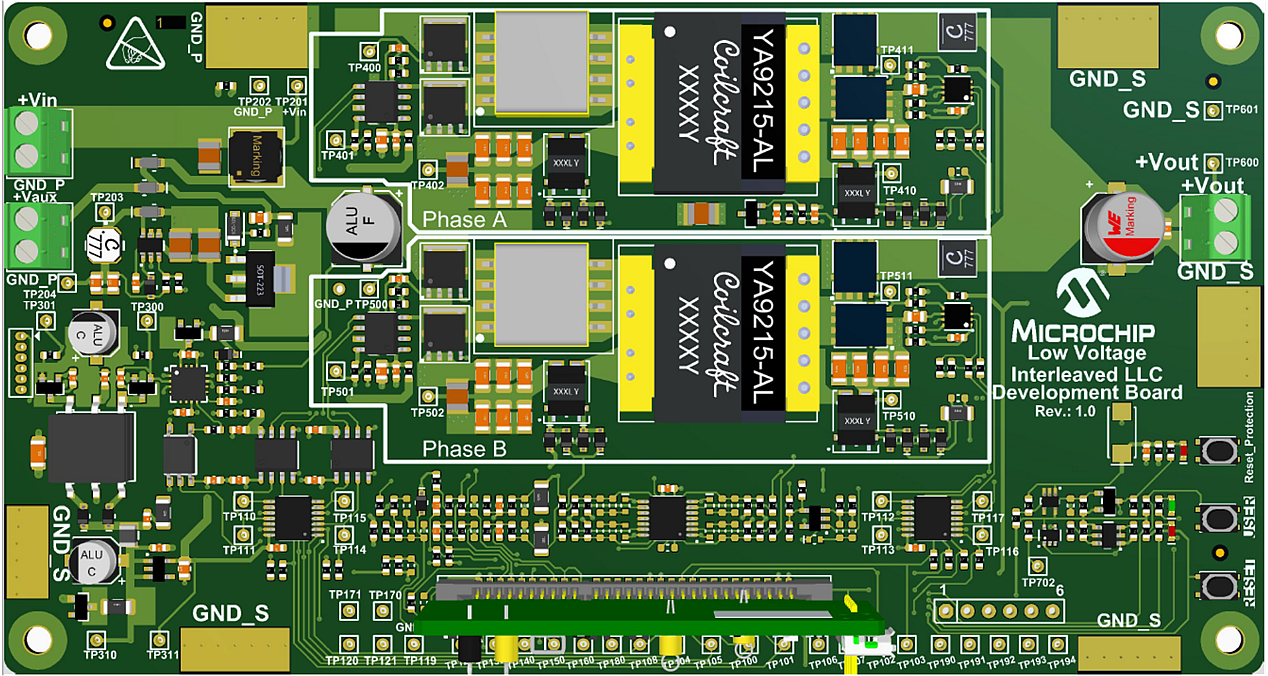
This solution demonstrates the implementation of an interleaved (2 phase) LLC converter using voltage mode control on the 50W Interleaved LLC Converter Development Board.
The 50W Interleaved LLC Converter Development Board is a generic development board for this topology that supports rapid prototyping and code development based on dsPIC33 devices. The board provides two identical half-bridge stages with LLC tank circuitry at the primary and voltage doubler rectification at the secondary. The board offers well organized building blocks that include an input filter, power stage, AUX supply, mating socket for Microchip’s newest Digital Power Plug-In Modules (DP PIMs), Human Machine Interface (HMI) and test points. The electrical characteristics are prepared to allow safe voltage levels of up to 50 VDC in and up to 12 VDC out. Topology and design are scalable and can be easily turned into real industrial demands targeting 400 VDC or 800 VDC bus operating voltage. A mating socket for dsPIC33 plug-in modules allows the system to be evaluated with different controllers. The pinout is compatible for EP, CK and CH dsPIC® DSC DP PIMs. A Human-Machine-Interface (HMI) and test points allow for easy evaluation and debugging.
Firmware documentation
Hardware Documentation
Target Device Documentation
Please always check for the latest data sheets on the respective product websites:
In this section we describe how to bring up the board both in open loop and closed loop modes, and with and without using the Power Board Visualizer GUI.
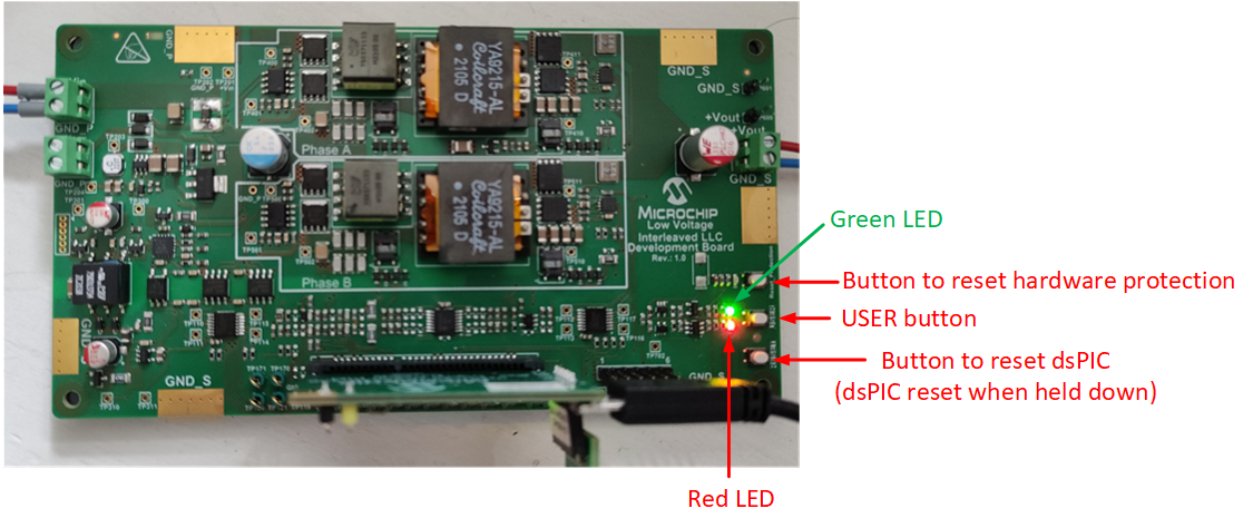
The interleaved LLC board has a simple Human-Machine-Interface (HMI) with LEDs showing status, and push buttons for control. This is shown below.
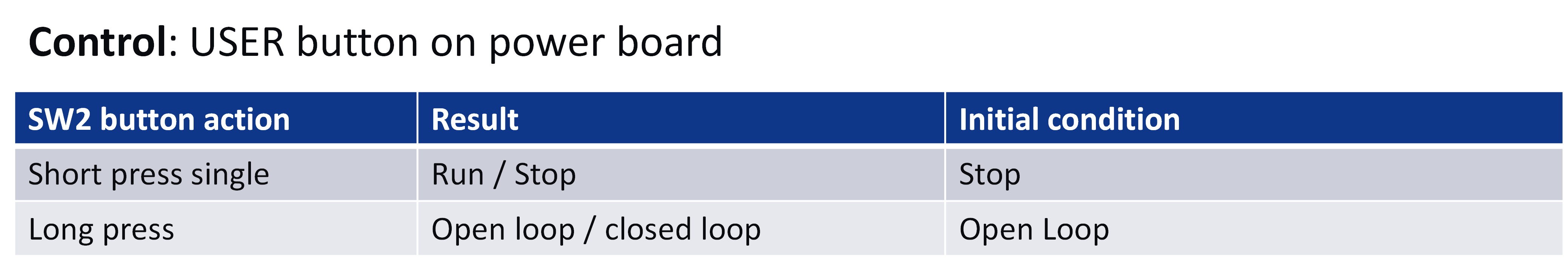
The USER button control action is outlined in the table below.
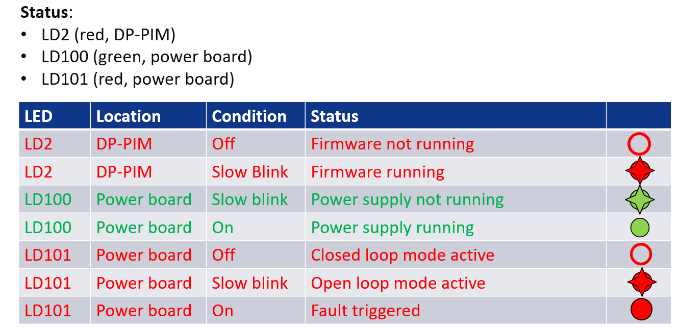
The board status as shown by the LEDs on the ILLC power board and the DP-PIM is outlined below.
The hardware connections for running the board in open loop mode is shown below.
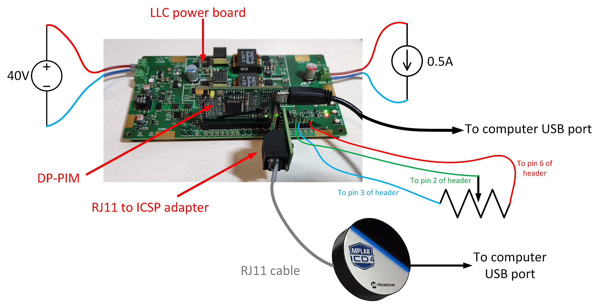
Note that we use the ICD4 in-circuit debugger to program the dsPIC, but any type of Microchip In-Circuit Debugger can be used here.
Please follow these steps to run the ILLC board in open loop mode.
(1) Connect computer directly to DP-PIM via USB cable (USB Micro Type-B on DP-PIM).
(2) Connect computer to ICD4 via USB cable, connect ICD4 to 6 pin header on DP-PIM via RJ11 cable and RJ11 to ICSP adapter.
(3) Connect poti (5kR or 10kR) to 6 pin header on LLC power board as shown above.
(4) Set poti wiper to max setting.
(5) Connect input terminal of LLC power board to DC source capable of providing at least 40V. Leave DC source off for now.
(6) Connect scope probe to TP100 (this is phase A high-side primary drive signal) ensuring to ground the scope at GND_S (not GND_P).
(7) Connect a voltmeter to the output terminals of the LLC power board.
(8) Connect output terminals of LLC power board to resistive or constant current load (set current load to around 0.5A or resistive load to around 20R), turn on the load if it is an e-load.
(9) Open ILLC project in MPLABx. Set as the main project, then download the firmware to the dsPIC on the DP-PIM.
(10) When the firmware is running, you should see
(11) Set the DC source to 40V. Set current limit to 1.2A or lower. Turn on DC source.
(12) Short press the USER button on the LLC power board. This turns on the converter. The status LEDs should behave as follows:
(13) Check the PWM signal on TP100 with an oscilloscope. The signal should have a frequency of around 1MHz, and a duty cycle of 45%.
(14) Check the output voltage with the voltmeter: with 0.5A load, it should be around 7.4V.
(15) Move the poti wiper slowly towards the min setting. While doing this, observe the signal on TP100 and the output voltage, you should see the frequency of the signal on TP100 decreasing, the duty staying (approximately) the same, and the output voltage increasing.
(16) With the poti wiper at the min setting, the signal on TP100 should have a frequency of 800kHz and a duty cycle of 45%. With a 0.5A load, the output voltage should be around 10.7V.
Note that at power-up, the firmware checks if a potentiometer is connected, and if so, the voltage on the potentiometer wiper sets the output voltage reference. If a potentiometer is not connected, the output voltage reference is fixed at 9V. The firmware will not detect that the poti is present if the poti is connected after power up, so you need to reset the dsPIC if this is the case.
Using the board in closed-Loop mode creates a controlled stable output voltage. It must be independent from input voltage or load changes. The reference for the output voltage can be set with a potentiometer and/or with the Power Board Visualizer GUI.
We discuss using the Power Board Visualizer GUI in the next section.
With Microchips Power Board Visualizer GUI we can easily visualize values and states visible on the ILLC Demo Board. We can also change the output voltage reference (closed loop only) and switching frequency (open loop only) on the running power supply with the GUI.
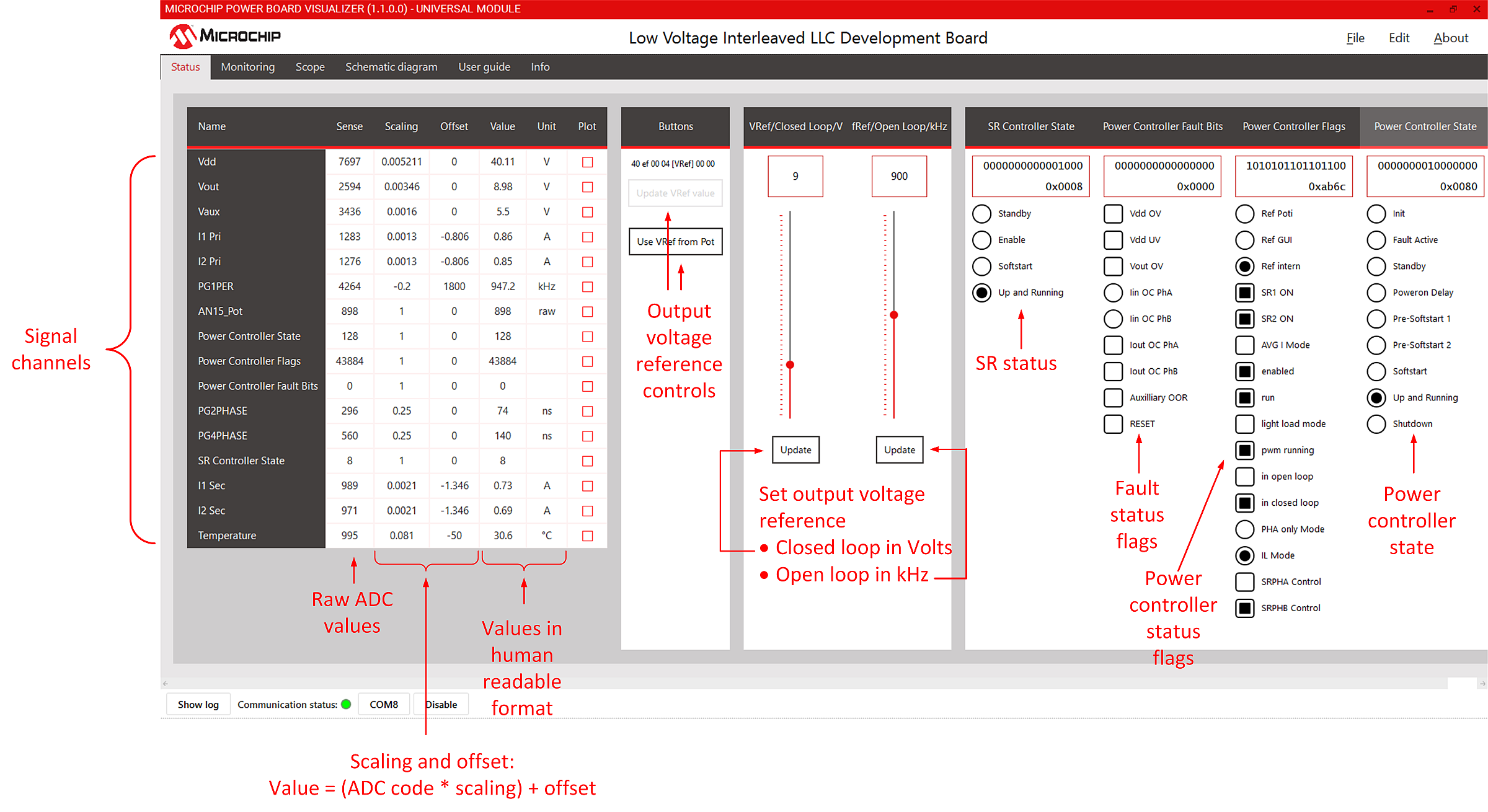
On the "Status" tab we show an example below with the main values like voltages and currents as well as status bits from the power controller and Faults.
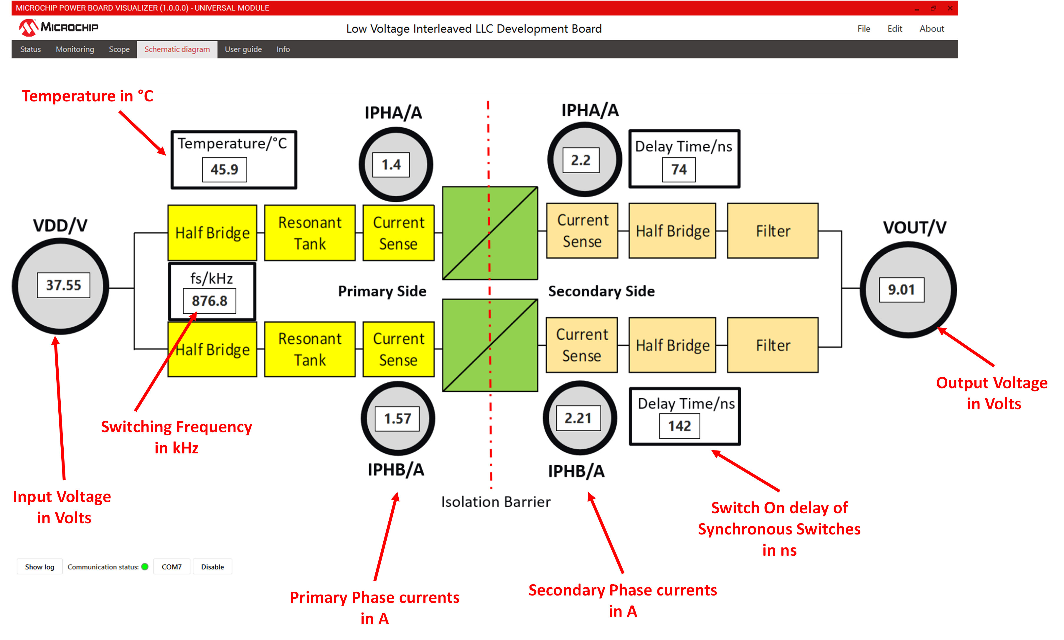
On the "Schematic diagram" tab there is the power supply block diagram with online updates of the most important values for easy understanding the working principles. This is shown below.
© 2021, Microchip Technology Inc.
