<img src="images/microchip.png" alt="MCHP" width="200";">
# dsPIC33C High-Resolution PWM and Comparator Configuration: Lab 8 **Fault-Triggerred PWM Shut Down**

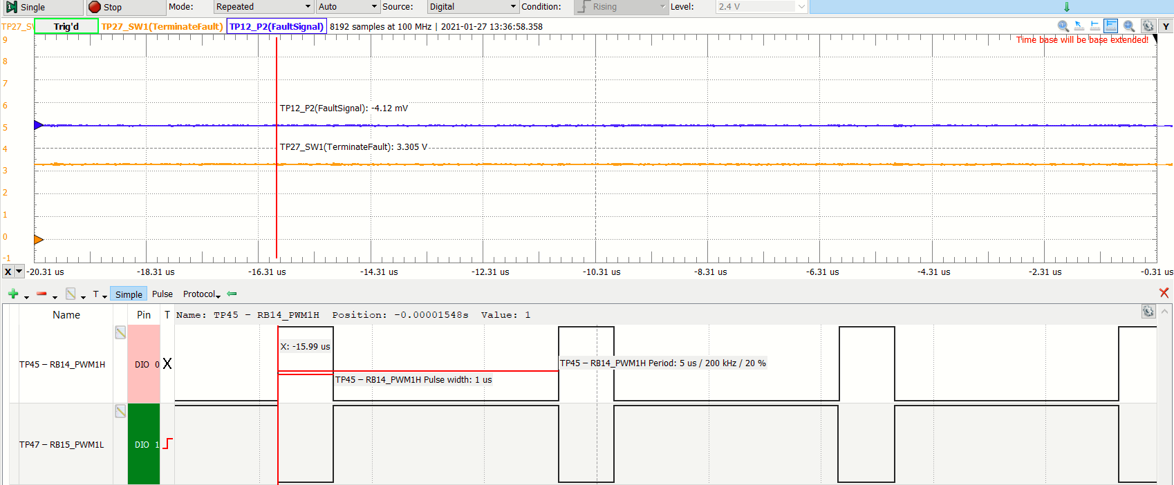
*Complementary PWM waveforms with 200 kHz and 20% Duty Cycle Switching Frequency Output; Fault Signal coming from potentiometer P2; Terminate Fault Switch* The potentiometer P2 voltage which acts as the fault source is adjusted from 0 to 3.3V. Upon reaching 2.5V the PWM signals are shut down.

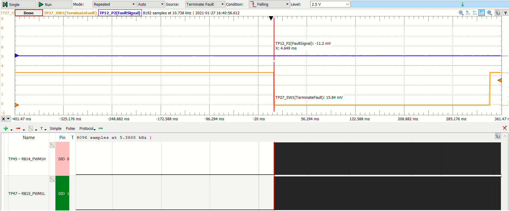
*Complementary PWMs are shut down by the Comparator Fault Source upon reaching 2.5V Fault Reference* In the condition that the fault signal is removed, the PG1 remains on shut down and the complementary PWM waveforms returns only upon pressing on-board push button *USER* on the Digital Power Development Board.
*Complementary PWMs are revived once the fault signal is removed and [USER] pushbutton is pressed to terminate the fault event.* Please refer to section *FIRMWARE QUICK-START GUIDE* below for more information on the initialization process and code structure.
- - - ## FIRMWARE QUICK-START GUIDE This code example builds on previous code examples showing how to use Microchip Code Configurator (MCC) to set up device clock domains. Although MCC also supports configuration tools for the High Resolution PWM module, PWM configuration in this example builds on generic peripheral drivers to help users better understand the peripheral architecture and key aspects of specific configurations and operating modes. In each PWM example code project the PWM configuration procedure is located in the user file pwm.c, where each register bit required to achieve/enable the specific function or mode of interest is set and its function described with comments. Once users are familiar with the architecture, features and capabilities, both configuration options (generic peripheral library or MCC) may be used. #### a) Project Directory Structure
The project contains four sub-directories 1. config: location of all hardware abstraction header files 2. common: location of generic peripheral drivers 3. MCC Generated Files: all device configuration files auto-generated by MCC 4. root: application user code On the hard drive, main.c/h are located in the MPLAB X project directory. All other user files, incl. peripheral drivers, are located in the sub-directory *sources*. Files generated by MCC are always located in their own sub-directory *mcc_generated-files* #### b) Using the generic PWM and Comparator peripheral driver
The PWM and comparator peripheral driver files p33c_pwm.c/h and p33c_dac.c/h provide data structures representing the Special Function Register (SFR) sets of PWM and Comparator instance as well as the PWM and Comparator base module. These 'virtual' PWM and Comparator objects are used to load, read and modify PWM and Comparator configurations without the need for hard-coded instructions, which would make the code hard to migrate from one peripheral to another or even across devices. To simplify the PWM and Comparator configurations, in these examples, each register is reset to a known default state before the user configuration of interest is set. Thus, only the register setting which really matters for a certain features/function are shown. To learn more about the generic PWM driver, its supported features and intended use cases, please read the comments inside p33c_pwm.c. #### c) Executing the Code Example
This code has been written to automatically start up and perform the function of interest. Please read the demo instructions on top of file main.c to learn more about the code example, test points, expected signals and demo mode operation. - - - © 2020, Microchip Technology Inc.