 |
Digital Power Starter Kit 3 Firmware
dsPIC33C Boost Converter Voltage Mode Control Example
|


|
|
Digital Power Starter Kit 3 Firmware
dsPIC33C Boost Converter Voltage Mode Control Example
|
|

Voltage mode control example for the boost converter on the Digital Power Starter Kit, version 3 (DPSK3) featuring the dsPIC33CK family of devices.
This code example demonstrates the implementation of a simple voltage mode control loop for the asynchronous boost converter. The loop implementation also includes the required state machine managing board status analysis, start-up control, operation monitoring, fault handling and auto-restart capability. The boost converter state machine is based on a generic library package, which is configured and executed in user code.
This code example also includes the LCD driver allowing users to observe runtime data on the on-board LC display. The on-board user switch USER is allows users to change the active display page to observe input voltage, output voltage, output current and board temperature.
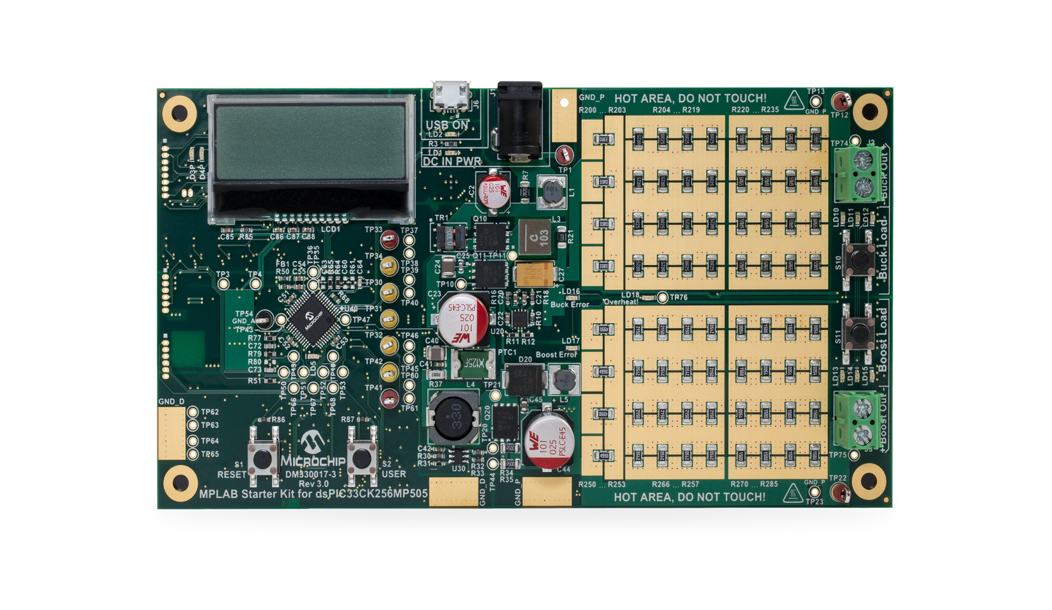
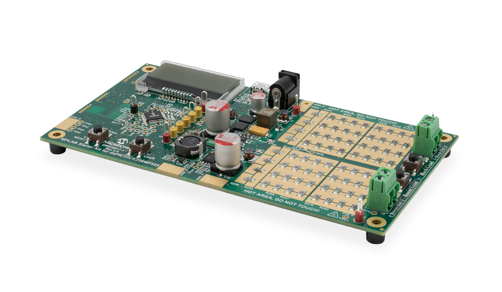
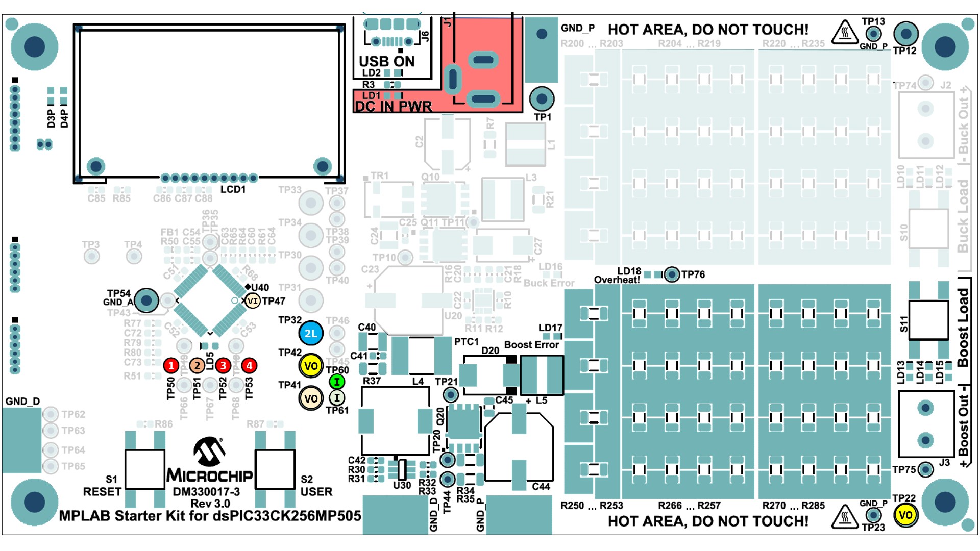
a) Power Supply Circuit
b) Protection Circuit
c) Communication, Programming/Debugging and Housekeeping
Unattended operating power supplies are always a potential safety risk as short circuits or failures of power components can occur at any time where even seemingly small power converters can cause fire or damage connected equipment.
After the device has been programmed and the target device starts up, the LC display will show the startup screen for approx. 3 seconds before switching to the runtime data display, showing the most recent input and output voltages. In case an appropriate power supply has been attached to the DPSK3 power input and the firmware is running correctly, the display should show an output voltage of +15.0 V DC.
When pressing the on-board button USER for one second or longer, the screen can be switched between:
By pressing the Boost Load on-board push button on the right edge of the board for less than a second, changes the static load level in four steps:
(value accuracy +/- 10%)
By pressing the Boost Load on-board push button on the right edge of the board for longer than a second, the load switches into stepping mode.
Pressing the Boost Load on-board push button again for less than a second, the step load can be adjusted between
(value accuracy +/- 10%)
For more information, please read the Digital Power Starter Kit 3 User Guide.
© 2021, Microchip Technology Inc.